04B-060 – Common Base Amplifier

A foundational BJT amplifier for teaching gain, biasing, and small-signal response.

PCB Details

Part No: 04B-060

Title: Common Base Amplifier

Board Size: Approx. 50 x 50 mm

Pieces per Panel: 4

Panel Size: 100 x 100 mm (V-scored)
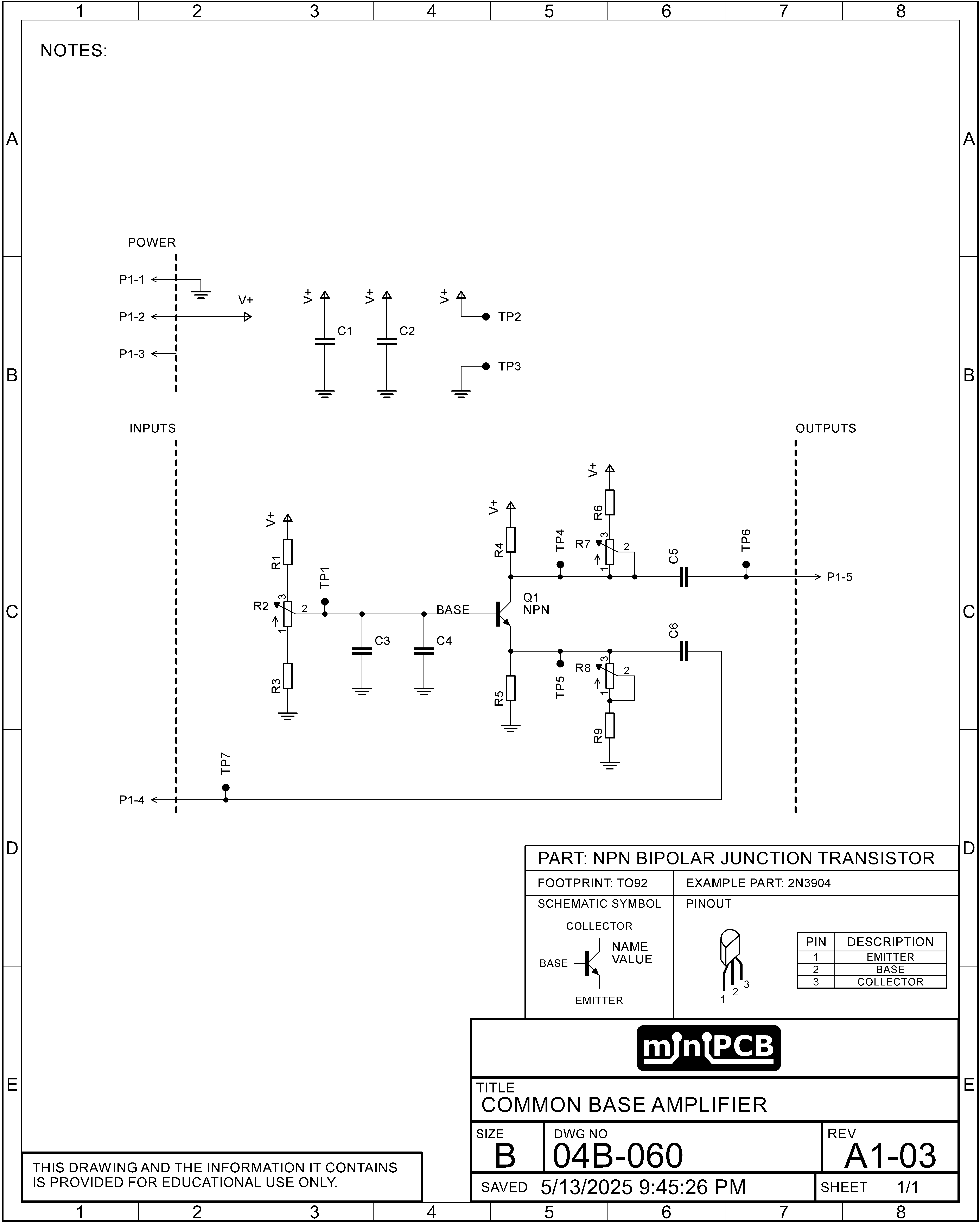
This miniPCB implements a single-stage common base amplifier, designed around a discrete NPN bipolar junction transistor (Q1), with optional substitution for an N-channel MOSFET or JFET. This amplifier topology features low input impedance, high voltage gain, and excellent high-frequency performance. Unlike the common emitter configuration, the input signal is applied to the emitter (or source), while the base (or gate) is held at a fixed bias voltage, and the output is taken from the collector (or drain).

Power Supply Conditioning

C1 and C2 are power rail decoupling capacitors that help suppress high-frequency noise and stabilize the DC supply voltage. TP2 and TP3 provide convenient access to the positive supply (V+) and ground (GND), respectively, for measurement and diagnostics.

Biasing Network

The base (or gate) voltage is set by a resistor divider network consisting of R1, R2 (a multiturn trimmer), and R3. This network establishes the transistor’s quiescent bias point. Fine tuning of the base/gate voltage is performed using R2, allowing precise control over operating conditions. To further smooth and stabilize this bias node, C3 and C4 are included as filtering capacitors. TP1 allows direct measurement of the base (or gate) voltage.

Input and Emitter (Source) Network

The input signal is capacitively coupled through C6, an AC coupling capacitor that blocks DC and delivers the signal directly to the emitter (or source). The emitter is grounded through an adjustable resistance network formed by R5, R8 (a trimmer), and R9. Adjusting R8 modifies the emitter resistance, which in turn affects both DC bias and voltage gain. TP5 provides access to the emitter (or source) node for measurement.

Collector (Drain) Network and Output

The collector (or drain) is connected to the supply rail through a resistive load composed of R4, R6, and R7 (a multiturn trimmer). This network sets the collector load and directly influences amplifier gain and output swing. Adjusting R7 allows fine control over these parameters. The amplified output is taken from the collector and passes through C5, an output decoupling capacitor that removes the DC offset. TP4 allows measurement of the collector (or drain) voltage, and TP6 provides direct access to the output signal.

Transistor Configuration

Q1 is the active gain element, installed in a TO-92 footprint with a C-B-E (Collector–Base–Emitter) pinout. The board is optimized for use with standard small-signal NPN BJTs, and is also compatible with many N-channel MOSFETs that follow the same pinout. However, most JFETs do not conform to this pinout and are not drop-in compatible without modification. This design allows users to experiment with different transistor technologies while maintaining the same amplifier topology and supporting circuitry.

Schematic

Board Layout

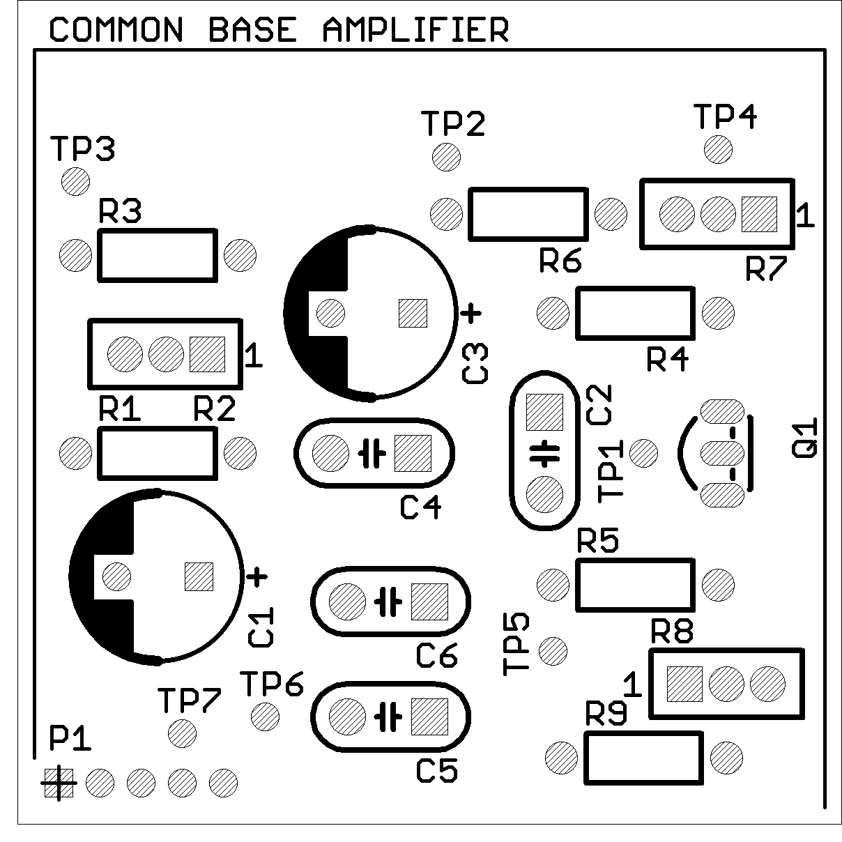
Top view of miniPCB

YouTube