How It All Started
My electronics journey began in 2003. By 2004, I had designed my first circuit: a flashlight-tag sensor. But the fabrication was ugly, and I only made one.
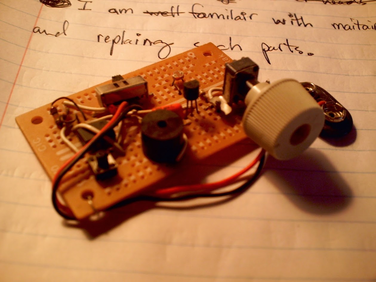
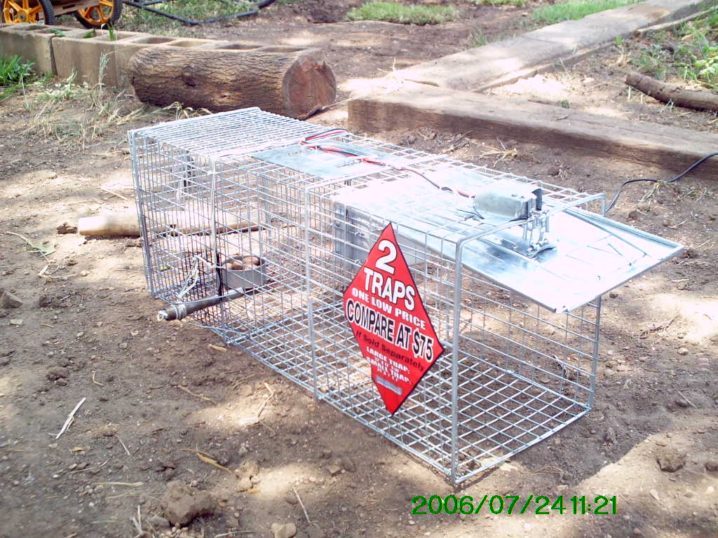
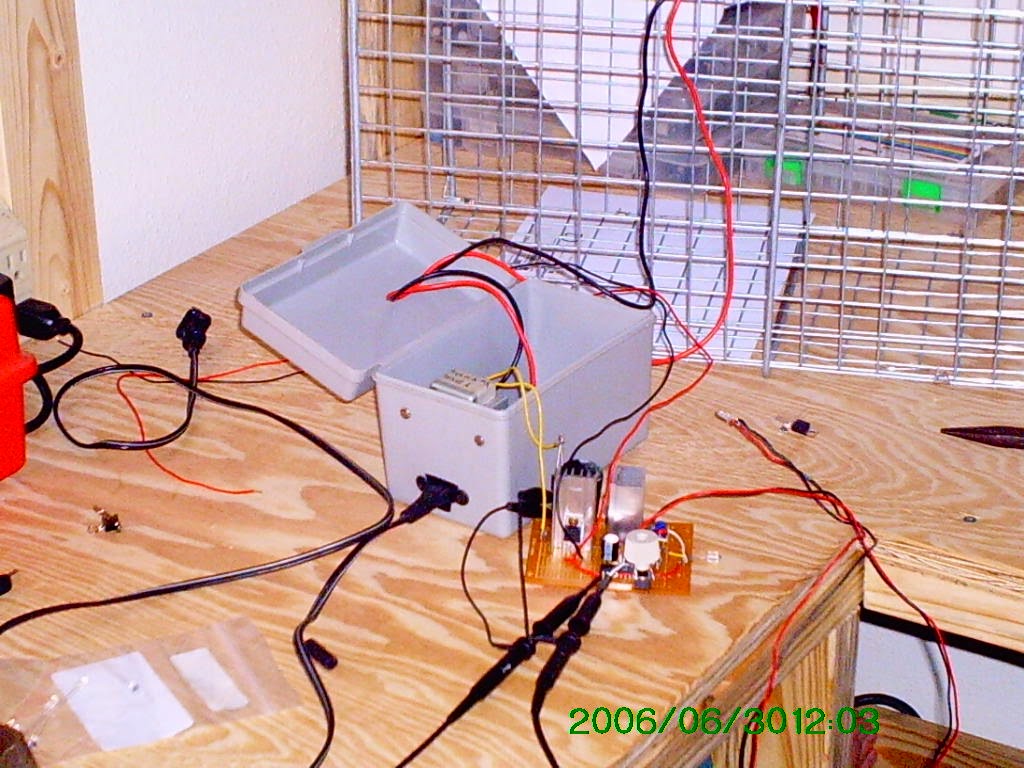
In 2006, I modified an animal box trap by replacing its mechanical trigger with an infrared LED and phototransistor. This project convinced me to pursue electrical engineering in college.
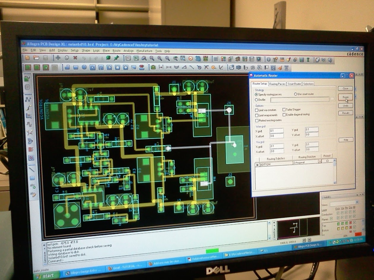
My PCB design journey began in 2011, in a lab at college. The PCB worked, but I didn't really know what I was doing.
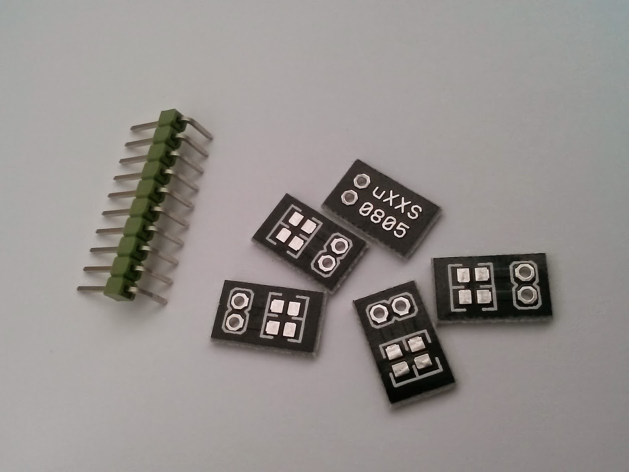
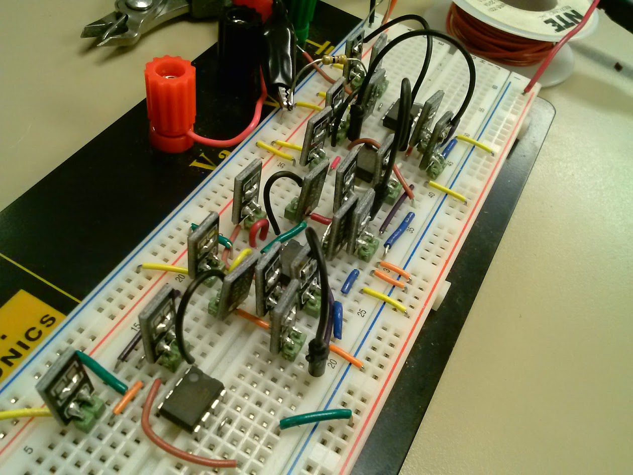
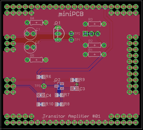
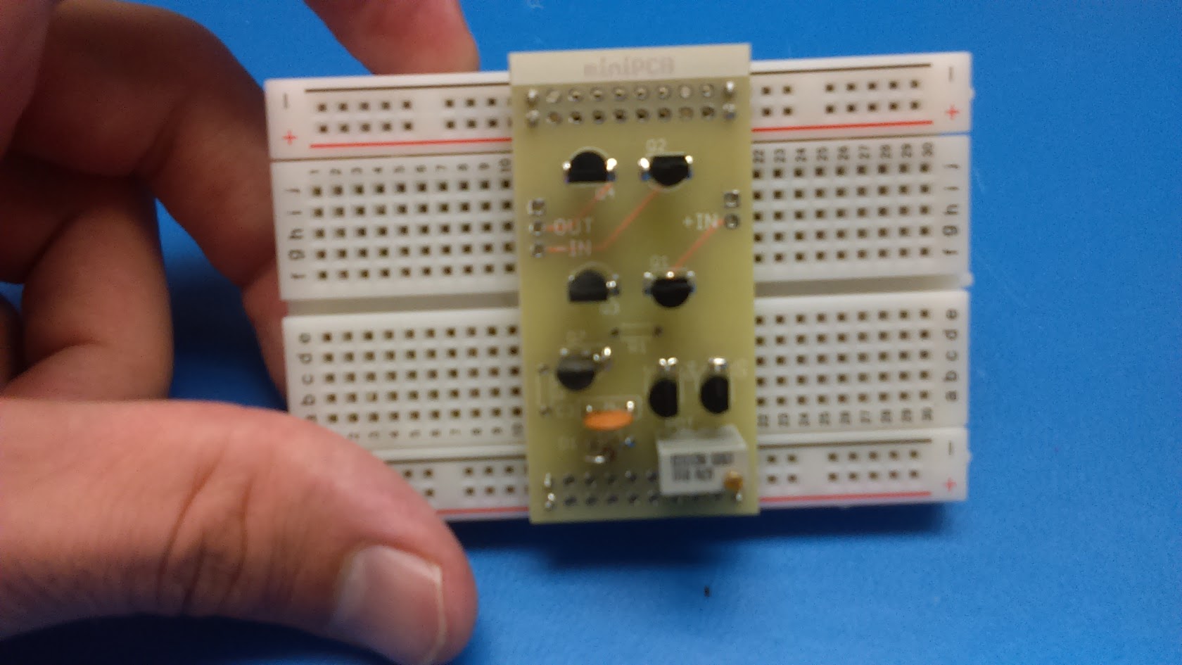
I started using the name miniPCB in 2014. The original idea was to create small PCBs with simple, even mundane, circuit layouts—like two components in series or parallel, etc. The goal was to build a collection of boards for educational, hobby or prototyping use. They didn’t work well when I tried to apply them to an audio filter.
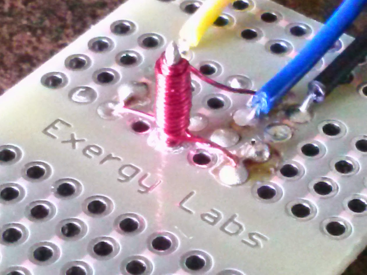
Interesting side note: in 2014 I created a small transformer on a PCB and tested it in the lab. It resonated around 2MHz, which was a fun experiment but not very practical. But I feel like that was a good experience to have.
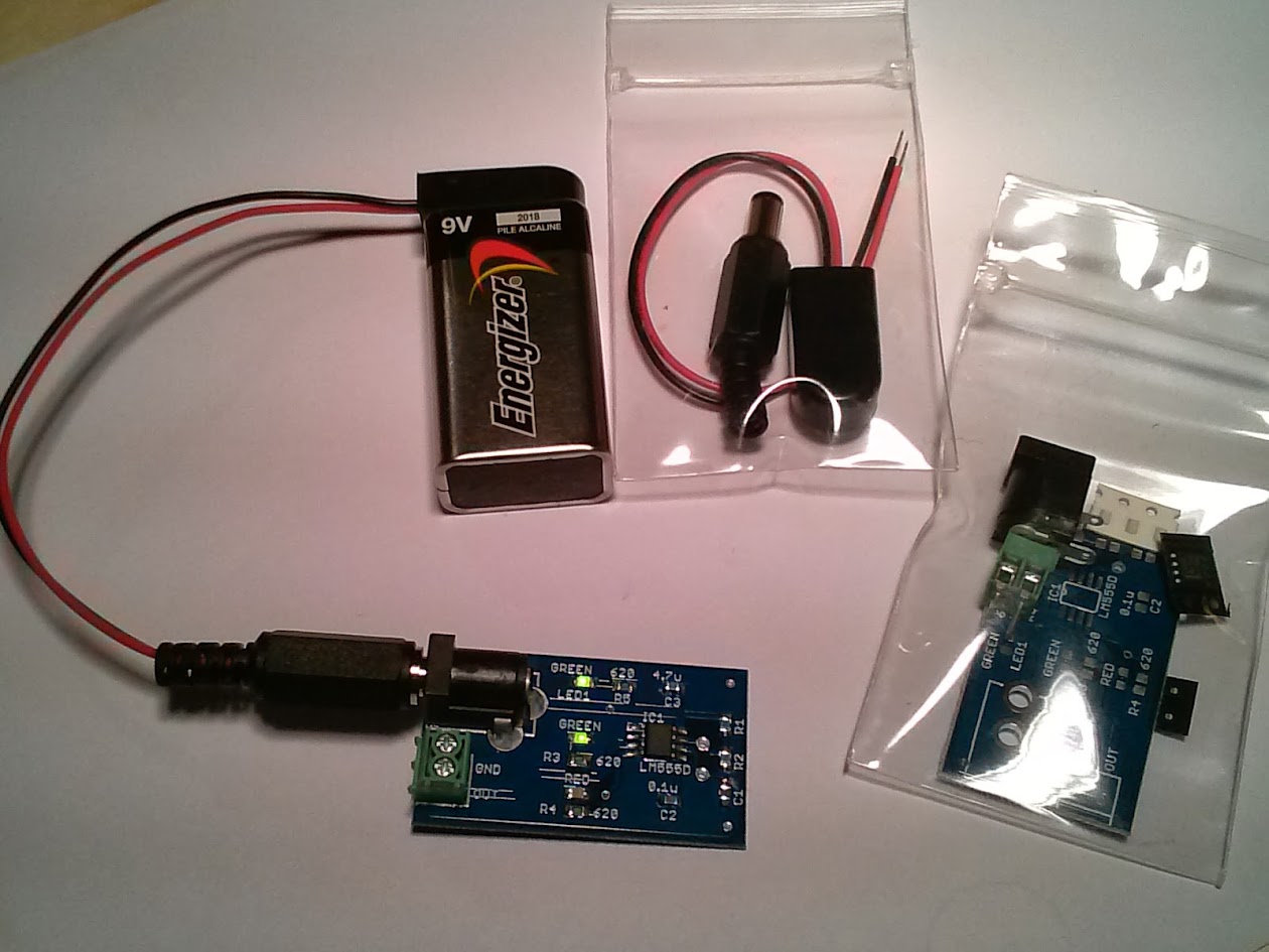
I also made a surface mount 555 Timer kit in 2014. But my documentation was lacking, and I never sold any. The kit was a fun experiment, but it convinced me I didn't want to sell kits. Just bare boards.
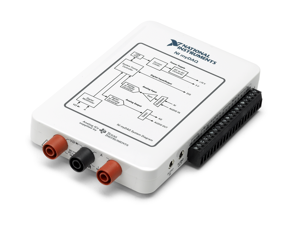
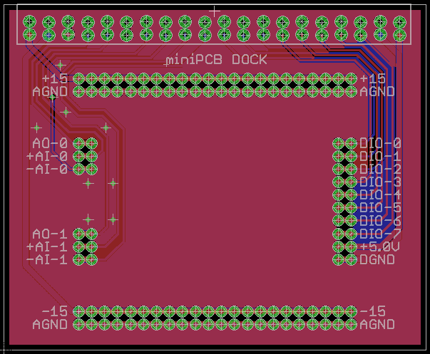
In 2015, I had the idea to create boards that interfaced with the National Instruments myDAQ, a popular educational tool at my university. I struggled to find a design that worked well, and eventually abandoned the idea in 2017.

From 2015 to 2020, I slowly worked through ideas for a useful collection of boards to teach electronics. I felt like I was on the verge of a great idea, but not quite there. My CAD skills gradually improved, and I started to create more polished designs. I also experimented with different form factors and layouts.
From 2018 to 2021, I created the miniPCB logo and icons. I experimented with putting the logo on the boards, but it took up too much space. So the boards today are minimalistic with a title and perimeter line.
In 2022, I created the miniPCB Design Standard and produced several circuit designs with part numbers that are still in use today. The form factor and features have only slightly changed since then.
In 2022, I also created a YouTube channel to document my journey and share my designs. You can see me struggle with the first designs, and how I gradually improved my skills.
In 2025, I created this website. The goal is to provide a central place for educators to learn about miniPCBs, access designs, and request sample boards. I also started reaching out to educators. I think we finally have a small collection of boards that can be useful in the classroom.