PCB Details
Part No: 04B-345
Title: Cascade Amplifier
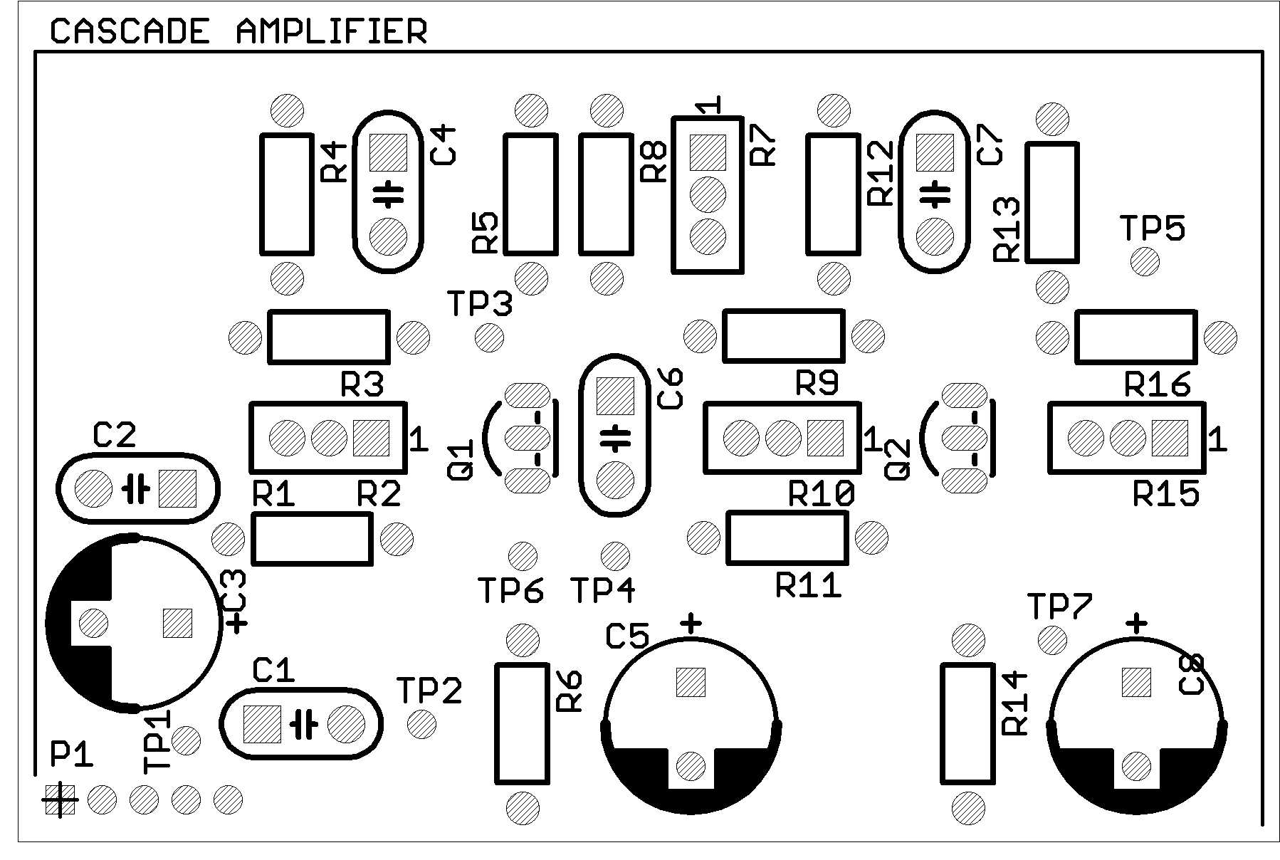
Board Size: Approx. 75 x 50 mm
Pieces per Panel: 2
Panel Size: 75 x 100 mm (V-scored)
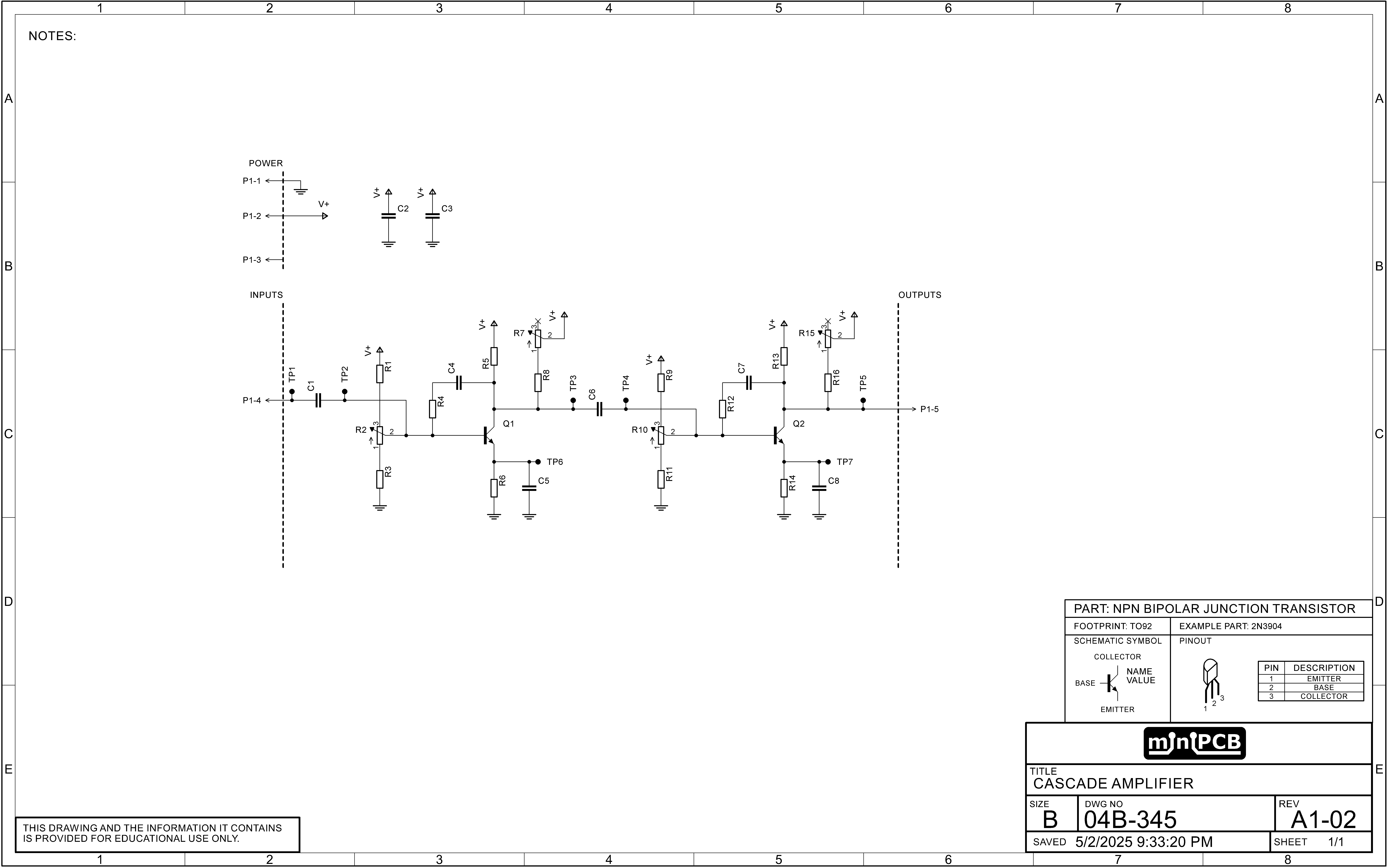
This miniPCB implements a two-stage cascade amplifier using discrete NPN bipolar junction transistors (Q1 and Q2), each configured in a common emitter configuration. The cascade topology multiplies the gain of two amplifier stages, providing significantly higher overall voltage amplification while maintaining phase inversion. This circuit serves as a practical platform for studying multistage biasing, interstage coupling, feedback, and gain control techniques. The board also supports substitution of compatible N-channel MOSFETs for extended exploration.
Power Supply Conditioning
C2 and C3 are power rail filtering capacitors that stabilize the supply voltage and suppress high-frequency noise. These components ensure consistent DC conditions for both stages and improve signal integrity throughout the circuit.
Input Coupling and Stage 1 Biasing (Q1)
The AC input signal is coupled to the base of the first transistor Q1 through C1, a decoupling capacitor that blocks DC from the signal source. TP1 allows direct measurement of the input signal voltage.
The base voltage for Q1 is set by a resistor divider formed by R1, R2 (a multiturn trimmer), and R3. This network defines the quiescent operating point for the first stage. TP2 provides a test point to measure the base voltage of Q1.
Stage 1 Feedback and Load Network
A local feedback loop composed of R4 and C4 connects the collector and base of Q1, introducing frequency-dependent feedback that helps stabilize gain and bandwidth. The collector load for Q1 includes R5, R7 (trimmer), and R8, allowing for adjustment of the DC operating point and output swing. TP3 enables measurement of Q1’s collector voltage.
The emitter of Q1 is grounded through R6, with C5 providing AC bypass to maintain high-frequency gain. This combination helps set the emitter current and provides thermal stability. TP6 allows observation of Q1’s emitter voltage.
Interstage Coupling and Stage 2 Biasing (Q2)
Signal output from Q1 is passed to the base of Q2 through C6, an interstage decoupling capacitor that blocks DC while preserving the amplified AC signal. The base of Q2 is biased through a second resistor network composed of R9, R10 (trimmer), and R11, allowing control over the second stage’s bias point. TP4 is placed at Q2’s base for monitoring.
Stage 2 Feedback and Output Network
Q2 features a feedback network from collector to base using R12 and C7, similar to stage 1, to shape frequency response and maintain gain stability. The collector of Q2 is connected to the supply rail through a resistive network made up of R13, R15 (trimmer), and R16, forming the output load. TP5 is used to measure Q2’s collector voltage, which represents the final amplified output signal.
The emitter of Q2 is connected to ground through R14, with C8 serving as a bypass capacitor to preserve gain at higher frequencies. TP7 is provided for emitter voltage measurements of the second stage.
Transistor Configuration
Q1 and Q2 are both mounted in TO-92 footprints with a standard C-B-E (Collector–Base–Emitter) pinout. The board is optimized for use with general-purpose NPN BJTs, though many N-channel MOSFETs with similar pin configurations can be used as drop-in replacements. Most JFETs are not compatible due to differing pinouts and biasing requirements. This cascade amplifier offers an accessible way to study two-stage amplification, phase relationships, and the role of feedback and interstage coupling in practical amplifier design.
Schematic

Board Layout